Results from CAD Software
 I don’t get to see this kind of stuff too often, but a recent project that pushed me to the limits had some rewarding results. A local company, Crenshaw Lighting contracted me to make some 3D CAD data for pieces of a chandelier that is to go into the US Capitol. The completed piece is shown to the right. My CAD data and the intermediate cast
  pieces are shown below.
I have to admit, SolidWorks just did not want to complete some of these shapes. When we started the project, we didn’t have great definition of the shape required. We had some 2D representations, which don’t get you where y ou need to be for 3D models. The shapes could have been much better, and they could have taken 1/3 the time in other software. I did come close to giving up, but I knew that the shapes were “do-able”.
Once we started working through the 2D shapes and got some cross-sectional information in there, things started to pick up. Plus, once I knew that I didn’t have to worry about draft  or CNC limitations, that helped too. These parts were produced by 3D printing a wax pattern, making a ceramic cast, melting out the wax, then casting the bronze into the ceramic. You often talk about the lost wax process as some extreme and expensive last resort for unproducible product designs, but the process does have a place in one-off shapes where cost is not a primary concern.
The parts were hand finished, and then fitted onto a bowl to create the finished piece. I didn’t work on the entire shape, just two areas of it.
I have worked on shapes like this for wooden furniture before, and people often complain that hand carving these shapes the way it used to be done is prohibitively expensive. History-based CAD is not the best way to do it, it’s like chopping down the tallest tree in the forest with a herring, to borrow a classic. But it can be done if you bang your head against it long and hard enough.

This is proof to me that CAD or geometry are not solved problems. Giving up on creating shapes so you can do something easy like accounting is really just abandoning your customers.
Anyway, I just got clearance from my customer to show these images and talk about the project a little. It feels good to get something like this in the “done” pile.

Really amazing and fantastic work…
CAD Services
GIS Services
@Dan Staples
Yes Dan we use both Sensable and Geomagic. Geomagic has some pretty good surfacing capabilities built into it too. We model outsoles for shoes (one of my more complex models is in the Solidoworks splash screens for 2012) and I have yet to find a shape that Geomagic won’t at least auto surface. These surfaces are not the greatest to work with downstream, but they do capture the shape nicely. The also have a parametric surfacer that requires the user to draw the boundaries, giving you the abililty to define where and how you want the surfaces shaped. Matt’s ability to create this kind of geometry in Solidworks is unbelievable and astonishing. GREAT WORK MATT!!!
Awesome work matt
Absolutely Amazing
First of all, Matt, UNBELIEVABLE work. The fact that this can be done in ANY nurbs-based CAD system is a testament to the AUTHOR (you) and not the tool. Nurbs-based CAD, no matter how good, is simply not well suited to ORGANIC work.
My knowledge on Sub-Ds is not deep but I think you would have a hard time achieving this level of precision with them. The nature of the subdivided cage, makes some of it tricky when trying to achieve a very specific thing. Maybe someone who’s done a lot of Modo can comment, but I think you could get something that “looks really good” but is not exactly what was asked for.
The right answer, as we’ve said before is SensAble Technologies Freeform. It totally eats this stuff alive, because it’s made for sculpting precise organic shapes, which is exactly the task here. They were recently bought by Geomagic, which is good news for their longevity (anyone here in the forum use Geomagic?). I only hope they can get it more widely distributed and available.
[Disclaimer. I used to work for SensAble, but my stock options are worth exactly zero dollars and zero cents, so I have no vested interested in their success. The technology is truly amazing for this type of work. It was totally capable of this when I left 10 years ago, so who the heck knows now what it can do.]
Matt,
What curves did you find most useful to define the leaf berry shape? Defining the shape is one thing, using features that do not fail sooner or later is another. I tend to choose a surface defined by the actual edges, rather pretending that I am using t-splines. The best surfaces are those with four edges, the lowest order curve that can do it will give the smoothest shape. I would probably leave sharp edges for your project as these surfaces will be easily hand finished and any casting porosity will show on an edge.
I have been using GeometryWorks, GW3d, for a few months. I find the surfaces much more reliable and correct with respect to boundary conditions. The conic surface has many forms of control that would be suitable for these kinds of shapes. The blend surface is also reliable and generates nicer “fillets.” The offset curve function is good for adding the right kind of slope control. All GW features do not consume their defining curves, so the same curve can be used to define adjacent surfaces. GW usually does something sensible at singular points, but it is asking for trouble to have two singularities on the same surface. GW features are compact and do not make the file size grow. The user interface for GW is a bit clunky, but not a problem as you need to do it one time.
Solidworks trims and knits can sometimes fail in cascade and vanish subsequent features. I hope my comment works as my iPad is complaining that 3G is not on the Internet.
Fantastic work, Matt. I’m constantly impressed by what I see you put out there. I can imagine there’s probably at least an equal number of difficult models you aren’t able to share images of.
Out of curiosity, do you have any idea what kind of printer was used to make the wax pattern?
@John Layne
Thanks, guys. This might be doable in SE, but it would need to be simplified a little. None of the really complex stuff worked in SW the first time. I had to come up with multiple methods to create some of the shapes. The fiddleheads in particular were tough to do.
The best software in my opinion would be a tug-and-pull software. So modo could probably do it. Alias. NX would do it. (Please don’t ask if I tried the Freeform feature in SW.) You need the ability to lay down a U-V patch with a specific flow, and then shape it. Subd’s can get away without the UV patch.
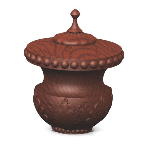
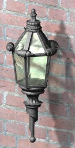
Here are some other examples of this kind of stuff I’ve done, these are all less detailed. I’ve definitely built up to this over time. The last one is probably the most complex of the lot.


Hi Matt,
Nice work, very challenging stuff I’d need a very clean calendar to attempt something like that.
Would this be doable in SolidEdge, I’ve been following the other blog with interest? It would be interesting to know how “easy” this would be in something like NX or Catia, any users out there care to comment?. What is the best tool for something like this?
Matt, awesome work. Could have used your skills years ago when I did outdoor architectural lighting products. Definitely a very challenging industry when it comes to intricate shapes.
@R.Paul Waddington
RPW, There are projects like this one, and one I did last winter for a sports helmet manufacturer that just drive me crazy. I don’t think I could not take these jobs, but I should quote 3X the price that I quote for them. I should just get NX, though, because I think these take years off of my life. The sense of accomplishment on a project like this is gratifying.
The real problem comes with, not making something the first time, but making unanticipated changes. Surfacing is a series of workarounds, and design intent with workarounds is non-existent. Small changes may mean an entirely new set of workarounds. I get so frustrated when small changes force you to make so many changes, like deleting and recreating fillets, using loft instead of boundary, or maybe a Fill just stops working, or gets spikes. This kind of stuff doesn’t make much sense, and are very time expensive to fix/change.
To some extent it comes down to project management. I try to get people to give me all the parameters and all the input right up front. They’ll even tell me they have done that sometimes, but then after they see my interpretation of their data, they suddenly find more information. And then sometimes it’s just an endless loop.
And the one I like best is “I need it ASAP”. Well, that’s not a date I can work to. Maybe “as soon as possible” is two weeks from now, because I’ve got 4 other “ASAP” customers in front of you.
Life as a CAD contractor has its ups and downs.
Congrats Matt: it’s attempting, and in this case completing, jobs like this which test operator and tool alike and, demostrate what is actualy possible given opportunity & a touch of tenacity.
If asked to do another of similar or of greater complexity would you accept or, has/does the experience suggest it would not be commercially sensible for you and or your customer?
It is interesting to guess what might be the intended stylistic components of sculptured shapes. I would guess that the feel when hand filing, sanding or scraping a surface is a consistant element. The treatment of edges may be a theme. The character of curves and inflections may be a theme. Your shapes will be more consistant than the hand carved and the shape attrbiute.
Very Nice!!
Well done Matt
We’ve got some customers doing some amazing things in metal and wood in Solid Edge. If you really want to get into some very sophistocated models, NX handles them well. This is a very nice job using Solid Works, but I’m not surprised at the amount of work involved. Very, very nice finished product.
@solidworm
Yeah, subd would be good. I can’t have a steady diet of that stuff, though, I need more machinable data usually. I don’t think these shapes would be much challenge for a subd modeler.
Amazing delicate details!
what’s the best option for modelling this kind of work? subdivision modeling could be a candidate given that stl files were needed.