Shape Challenge: Cinderella’s Slipper
 Since this challenge will be running while SolidWorks World runs at Disney, I thought it would be nice to do a Disney related theme. Kim suggested Cinderella’s glass slipper. Showing shapes in glass is difficult to do properly, so I’m showing it here opaque.
In this case, there are actually two challenges. One is the overall shape of the shoe, and the second is the heel. They both may be easier than they look. Let’s start with the main shape of the shoe.
Shoe Upper
Since this one is more involved than the Puffy Cube, I’ll show you how I did it, and then you can “try it on for size”, or make your own and share it with us.
The entire shoe took me 25 minutes to model, including the heel. The main body of the shoe is one continuous surface. This is the main trick in this part of the challenge. How do you make a shape with two rounded ends (heel and toe)?

Usually when I set up a part like this, I start with a layout sketch of some sort. In this case, the main shape I want to create is driven from a side view, so on the side plane I draw the red and blue lines in the image below. Notice I’ve also added a construction line to locate the floor. From the red and blue lines I’m able to judge where to place the sketch elements that create the shape of the shoe.

There are 5 gray sketches, which may be tough to see. Three of the sketches are simply ellipses. Two of the gray sketches, one at each end, are points. Sketch planes were established parallel to the Front plane at spline points in the blue spline which defines the sole of the shoe. Remember some of the tricks from the Spline Schmline tutorials for getting a straight section under the front of the shoe.
One of the things that this shows right off the bat is that its ok to build more than you need. As long as what you create makes the shapes you need, getting rid of extra stuff is not usually a problem. Of course this is a massive oversimplification of actual shoe geometry, but it serves our needs here to demonstrate technique.
 Some people may not know that loft and boundary features can use points at the ends of the features. Even if you knew that, you may not know that establishing tangency at the points causes the end of the feature to be rounded. Beyond that, the tangency can be weighted, with lower weights being pointier, and higher weights being rounder. To the left is the propertymanager of the boundary surface used to create the shape. The weighting is set to 10 for the point at the heel end of the loft.
That is really the bulk of the work on this part, and covers the main part of the challenge. The rest of this is just extra credit.
The red sketch is used to trim off the top of the shoe, leaving the opening.
The blue spline is used to create an extruded surface, and then the extruded surface is used to create a mutual trim with the main part of the shoe. This trim is easier if you have already done the top trim. If you have not done the top trim, you may need to switch from Keep Selections to Remove Selections. Visualization with Trim features can be tricky sometimes.
Shoe Heel
Ok, on to the heel. The main feature of the heel is that one of the profiles is a 3D face. Did you know you can loft directly from a face or surface body?
 To do this, I drew a line on the Top plane, and created a split line on the bottom of the shoe (on the extruded then trimmed surface). Then along with the two other sketched profiles, selected the split face at the back of the shoe.
I used a solid loft for this, not a surface feature. Lofting from a surface implies that you want to cap the ends, and capping the ends is usually a solid function.
Selecting the face by itself for me was not straight forward. Just selecting gave me the surface body, which I didn’t want. I just wanted the face. There are other methods of doing this, but I got at it by rotating the face so it was hidden from view and then using the Select Other option to get the face. Selection Filter would be a more direct way of doing that. “X” is the default hotkey for Select Face.
Note: In order to get this loft correct, you’re going to have to use connectors. Also be aware that connectors cannot be used if you have the Selection Manager showing.
I was not able to add a connector to the loft. The first thing I did was to Show All Connectors. This gave me everything I needed.
 You may notice that when lofting, the loft tries to twist like the image at the left. This is what the connectors are for. Connectors are a little like guide curves that you don’t have to draw. People who know a little bit about the topic may tell you that you have to use loft sections with the same number of elements. The sketches have 4 sides and the face has 2. You don’t really need to have the same number of sides. Connectors can be used to contol that.
Connectors are an entirely separate field of study. There are no dimensions, no relations, nothing to tie these things down. You can’t make connectors lie on a plane, or be symmetric. If you need to do that, you need to use guide curves instead of connectors.
The finishing touches for me were to thicken the shoe upper to the inside, and to put a full round fillet on the thickness face. A few small fillets on the heel make the renderings look a little nicer. Notice that the images here are all just RealView.
This looks like more work than it really is. Give it a try and report back with your results! Remember the two main points here are that you can loft/boundary from points or from non-planar faces. Download my model by clicking on the first image in this post.
To me the best way to learn is to try, especially when trying involves some actual thinking. I don’t think people learn much from following a set of step-by-step instructions. That’s not learning.
Best of luck to you!
ps: I’ll be reporting frequently from Orlando, so stay tuned.
=====================================
 The first entry comes from SolidWorm. I like it when people aren’t afraid to try stuff. The use of the Freeform feature here is probably an example I could follow, in fact you could take the idea much further.
If you check out the model and look at the OMG sweep at the bottom, notice that he gets some unexpected results. Click on the image to download the part.
Very nice try! This is an approach that has techniques that are certainly usable. Thanks for this submission, SolidWorm!
==========================================

Entry #2 is from Kyle Stellpflug. Kyle took a more literal interpretation of the shoe, modeling first the edges, then the faces. This is an approach I often take when I’m trying to be more precise about something. Kyle did something I wish I had done on mine. See how his boundary profiles are perpendicular to the general direction of the “flow” of the shoe? That’s nice. My profiles were straight up and down, while the shoe slants. Mine looks a little stretched around the ball of the foot. His looks more natural in that area. Anyway, nice job.
==========================================
 Entry #3 is from Leonardo Sanchez. Leonard used SolidThinking for the upper part of the shoe, and then brought that into SolidWorks, and continued from there. Leonardo modeled half of the shoe upper and mirrored it. I checked the Deviation Analysis in SolidWorks along the edges between the halves, and it is very good. Much better than SW is usually on its own. The deviation was 0. Not 0.1 or even 0.01, but 0. This means that SolidThinking can model tangencies very accurately.
This model is the most detailed one yet, in terms of actual finished detail like sole, heel bumper, and so on.

Here is the screen shot Leonardo sent from SolidThinking. I’m getting more anxious to do a real project in ST.
Click the image of the gray shoe to download Leonardo’s part and a couple of screen shots. Very nice job, and thanks for submitting this work from SolidThinking!

==========================================
Entry #4 from Mark Landsaat. More boundary surfaces, including a closed loop boundary. Extruded surfaces as reference and as model faces.
I investigated this part a little, because I haven’t worked with closed loop boundaries that frequently. I’m not picking on Mark here, I think his model is very interesting. This is the kind of investigation I do on my own models all the time, and I think it is the only way to gain a deeper understanding of how these software tools work – to basically reverse engineer them. No one is going to tell users this kind of thing if we don’t figure it out for ourselves.
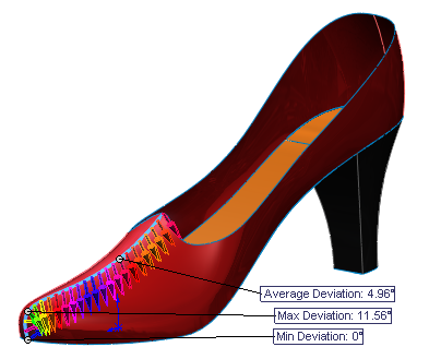
There is a little anomaly in the part that didn’t seem right. A closed loop boundary feature should give a continuous, smooth surface, but this one was split in two places. Notice the edges down the toe and the heel. The edge at the toe looked a little off, so I did a Deviation Analysis, and you can see in the image to the left how far off it is. This is an internal edge in a single boundary feature. It should be perfectly continuous.
It turns out that one of the trims uses a spline, and the spline touches the edge of the surface it is trimming, as shown below.

 Where the trim spline touches the edges causes the finished trimmed surface edge to be split rather than continuous, so the trimmed surface has a right edge and a left edge. Extending the surface so it is longer than the trim sketch fixes the problem, and the finished boundary surface is no longer split with internal edges, so it can no longer have that discontinuity across the toe.
Thanks to Mark for this interesting model. It’s a great opportunity to learn stuff.
=====================================
 Entry #5 is from Matt Sass, the winner of Rob Rodriguez’s Cobra rendering contest. Matt’s rendering of the Cobra car was published in the Surfacing and Complex Shape Modeling Bible.
More commentary after the SolidWorks World insanity subsides.